A request for 10 mm wear-resistant rubber for a chute may sound complete, yet it leaves the most important questions unanswered. Where does the material first hit? Is the surface wearing evenly, or is one joint opening before the rubber is used up? Has the feed changed since the last liner was installed?
Those questions matter because ore, concentrate, tailings and slurry do not load every part of a plant in the same way. Selecting rubber lining for mineral processing equipment means matching the compound, thickness, panel layout and attachment method to the actual flow path. The method below is intended for maintenance engineers, equipment builders and buyers preparing a quotation request.
The following is a composite scenario drawn from common lining-inspection questions; it is not presented as a named customer project. A rubber-lined transfer section shows exposed steel close to the feed area. The side wall still has usable rubber, one panel edge is lifting, and a long polished band runs toward the outlet. Production records also show that the particle mix and transfer rate have changed since the liner was fitted.
The first purchasing note calls for the same rubber in a thicker sheet. During the shutdown review, the team marks the material path on a drawing and labels three separate zones: direct impact at the entry, sliding abrasion along the wall, and an exposed joint at the panel edge. Remaining thickness is recorded by location, the joint is photographed, and the team checks which dimensions cannot change without reducing clearance.
The inspection changes the quotation request. Instead of asking for one thicker sheet across the whole section, the team sends the wear map, current panel layout and attachment details for review. The point is practical: identify what is loading each surface and where failure begins before deciding which rubber lining to buy.
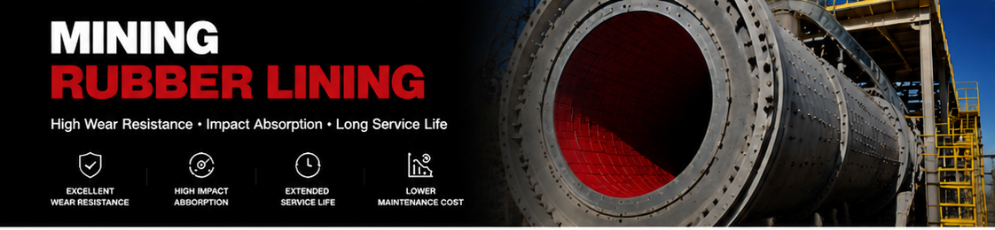
Mineral processing equipment rarely wears uniformly. The feed point may receive impact, a change in direction may produce concentrated abrasion, and a discharge area may see turbulence or particle accumulation. Joints, corners, bolt lines and unsupported edges can fail for reasons that are different from the exposed rubber surface.
Start by marking the entry point, direction of travel, impact location, transitions and discharge. Compare that flow map with the actual wear. If the most severe wear has moved since the previous inspection, check for changes in feed material, moisture, throughput, flow speed or equipment geometry before selecting the next lining.
Continuous sliding contact can remove rubber along the direction of material flow. Fine or sharp particles may polish, cut or score the surface. The wear record should show the flow direction and whether the loss is broad and even or concentrated in a narrow track.
Large particles or a high drop point can create local craters, cuts and deep gouges. An impact zone may need a different layout from a downstream sliding zone. Review the support beneath the rubber as well as the exposed surface, because a panel that moves under impact can expose its edge to further damage.
A lifted edge, open joint or blister is not automatically a compound problem. Inspect surface preparation, adhesive compatibility, moisture, fasteners, panel seating, backing condition and the direction of material flow. A new lining may repeat the same failure if the installation detail remains unchanged.
Nominal equipment size does not describe the full wear environment. The table below is a useful first page for an RFQ: record what is known, leave uncertain values clearly marked, and attach the drawing or photograph that supports each observation.
| Process parameter | What to record | Selection relevance |
|---|---|---|
| Handled material | Ore, concentrate, coal, sand, tailings or mineral slurry | Provides the starting point for reviewing the contact medium and wear pattern. |
| Particle characteristics | Approximate size, shape, hardness and whether particles are sharp or rounded | Helps distinguish sliding abrasion, cutting, gouging and impact. |
| Moisture and solids | Dry, damp, wet or slurry; solids content or density if available | Supports review of wet abrasion, flow behaviour and material compatibility. |
| Flow condition | Flow rate, pressure, speed, drop height and direction changes | Shows how strongly the material loads each zone and transition. |
| Environment | Temperature, oil, fuel, chemicals, cleaning agents and outdoor exposure | Helps determine whether a natural rubber compound remains suitable or needs further review. |
| Maintenance history | Installation date, inspection dates, wear locations and previous changes | Shows whether the issue is local, progressive or associated with a process change. |
Rubber lining changes the working surface of equipment. Before approving a thickness or panel arrangement, check internal diameter, passage area, flange faces, sealing surfaces, bolt holes, access openings and moving clearances. This is especially important for slurry pumps, close-fitting components, narrow chutes and lined pipe spools.
For tanks and hoppers, record the wall shape, corners, nozzles, manways, outlets and areas where material collects. For pipes, include straight sections, elbows, reducers, branches, flange details and the direction of flow. For a pump, identify the casing, impeller, side liner, suction area and discharge passage separately.
A dimensioned drawing is more reliable than a photograph alone. Photographs still matter because they show the actual wear, joint condition and access limitations. Send both when possible, and mark the most severe zone on the drawing.
Natural rubber is often considered for wet abrasive applications because resilience can be useful where particles repeatedly contact and move across the surface. That does not make one natural rubber formulation suitable for every mineral-processing duty. The final material review should include abrasion, impact, tear behaviour, temperature, chemistry and the way the liner is supported.
Where oil, fuel, solvents, aggressive chemicals or elevated temperature are present, ask the supplier to review compatibility rather than relying on a wear-resistant label. A material that performs well against abrasive slurry may require a different compound when the medium or cleaning process changes.
Also compare the complete scope, not just the rubber family. Thickness, hardness, sheet dimensions, cut pieces, moulded parts, edge treatment, backing, adhesive or fasteners can all affect the practical result. The lowest price per square metre may not represent the same technical scope as a fabricated or equipment-specific lining.
Thickness provides wear allowance, but it also adds weight and can reduce clearance or flexibility. A thick sheet may be unsuitable in a narrow passage, while a thin sheet may leave too little allowance in a severe impact zone. Consider a zoned layout when different parts of the equipment have clearly different loading patterns.
Hardness should be reviewed together with resilience, abrasion resistance, tear strength, temperature and the dominant wear mechanism. Choosing the hardest available rubber is not a complete selection method. A softer resilient compound may be considered in one impact condition, while another location may need different dimensional stability. The equipment and service data must decide the review.
The mining rubber lining thickness and hardness guide explains these two properties in more detail. If the existing liner has already failed, use the rubber lining failure inspection and replacement guide to document the damage before requesting a new specification.
| Equipment | Review first | Useful RFQ evidence |
|---|---|---|
| Chutes and hoppers | Impact point, material trajectory, transition edges, panel support and outlet flow | Flow sketch, drop height, internal dimensions, wear map and panel layout |
| Pipes and elbows | Particle direction, bend radius, internal diameter, joints and flange clearance | Spool drawing, pipe schedule, elbow details, slurry data and worn-area photographs |
| Tanks and vessels | Liquid level, settled solids, corners, nozzles, access and chemical exposure | Tank drawing, lining zones, operating temperature, medium and attachment plan |
| Slurry pumps | Casing, impeller, side liners, suction and discharge passages, clearances | Model, part number, component drawing, slurry data, speed, pressure and wear history |
Chute liners should follow the real material path. The feed zone may need to handle direct impact, while a side wall may mainly see sliding wear. Check upstream edges and joints because a small step can catch particles and start lifting. The rubber chute liners for mining selection guide provides additional application context.
For a rubber lined tank or pipe, geometry and sealing details are as important as the rubber surface. Identify areas that must remain clear and record whether the lining is bonded, mechanically retained or supplied as replaceable sections. For connected slurry pipework, review the slurry pipe rubber lining specification guide.
Slurry pump components should be reviewed individually because the casing, impeller, suction area and side liners may experience different wear. Provide the pump model and part number with drawings or accurate measurements. The slurry pump rubber lining selection guide covers the main wear zones and RFQ details.
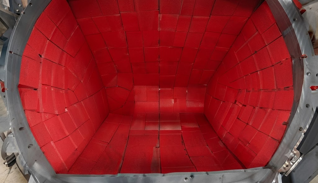
Attachment method should be selected with the substrate, equipment movement, access, maintenance plan and operating environment in mind. Bonded lining can provide a continuous surface when preparation, cleanliness, adhesive compatibility and curing conditions are controlled. Mechanical fastening can be useful where panels need to be removed, but fastener heads, holes and joints must be positioned so they do not become premature wear points.
Replaceable panels can make sense where wear is concentrated and access is practical. The panel layout still needs a supported edge, suitable joint direction and enough clearance for removal. A supplier should review the lining and attachment as one system rather than quoting a sheet without installation assumptions.
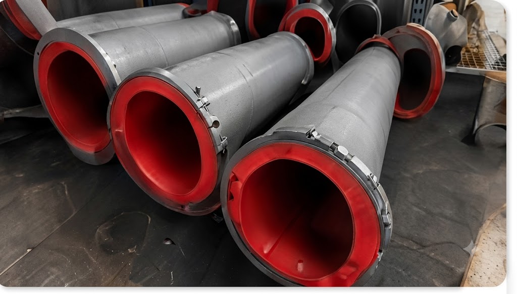
Use the following checklist when requesting a rubber lining quotation. It helps suppliers separate a material-only request from an equipment-specific lining requirement: For a focused checklist of drawings, wear zones and operating data, see our mining mining rubber lining RFQ checklist
If a value is unknown, say so. A marked-up drawing and a short explanation of the failure often provide more useful starting information than an assumed specification.
Record the starting condition after installation: material description, thickness, hardness, panel locations, attachment method and operating settings. At later inspections, photograph the same reference points and note where the wear has advanced. This creates a simple comparison between the original assumption and the actual plant condition.
When the next replacement is needed, the service record can show whether the issue is uniform abrasion, a single impact zone, a process change or an attachment detail. That history helps the supplier discuss a better-defined mineral processing rubber liner instead of repeating the same generic order.
No single lining specification fits every equipment type. Material, particle behaviour, flow, temperature, chemistry, geometry, thickness, hardness and attachment method all affect the decision.
It may be suitable for some abrasive wet duties, but the tank medium, solids, temperature, chemical exposure, corners, nozzles and attachment method must be reviewed. The required lining should be defined from the equipment drawing and operating conditions.
No. Impact, sliding and low-load zones may have different requirements. A zoned arrangement can be considered when the equipment geometry and transitions support it.
Send equipment identity, drawings or measurements, material and process data, current lining details, wear photographs, required quantity and installation constraints. These details allow the supplier to review material and scope together.
Qihang Rubber supplies mining rubber lining and wear-resistant natural rubber sheet for abrasive equipment applications. Send equipment drawings, material information, operating conditions, photographs, dimensions and quantity through the Qihang Rubber inquiry form.
With that information, the quotation can define the inspection and replacement scope, material, thickness, fabrication and installation assumptions. For connected equipment, the slurry pump rubber lining guide and slurry pipe rubber lining guide provide component-specific checklists.
Tianjin Qihang Plastic Technology Co., Ltd
12+ Years Expertise in Industrial Rubber Sheet Manufacturing • Global Export Leader • REACH/RoHS Certified
...[ Read More >>]


