Mining transfer points expose chute surfaces to a difficult combination of sliding abrasion, repeated impact, vibration and material build-up. A rubber chute liner should therefore be selected from the actual duty of the equipment, not only from a nominal sheet thickness or a general material name.
This guide explains the information that purchasing, maintenance and engineering teams should review before requesting rubber liners for chutes, hoppers, bins and conveyor transfer points. It covers wear mechanisms, rubber selection, thickness and panel layout, fixing methods, inspection planning and the details needed for an accurate quotation.
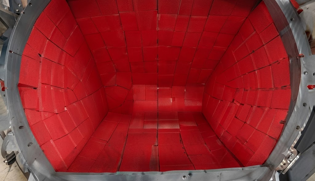
When the application includes slurry transport through pipe spools or elbows, use the Slurry Pipe Rubber Lining Specification Guide to prepare the pipe dimensions and operating data.
A transfer chute changes the direction and speed of conveyed material. Ore or aggregate may strike the loading zone, slide along the chute wall and then accelerate toward the discharge. The liner must deal with more than one wear mechanism, and different areas of the same chute may require different panel dimensions or thicknesses.
Because these conditions interact, the most useful starting point is a wear-zone drawing. Mark the impact point, the sliding path, the discharge area and any locations where the existing liner has lifted, torn or worn unevenly.
Transfer chutes guide bulk material from one conveyor to another. Liner selection should consider the material trajectory, belt speed, transfer height, particle size, chute angle and the space available for installation and replacement.
Hoppers and bins can combine impact at the inlet with sliding wear near the outlet. Corners, transitions and narrow discharge sections deserve separate attention because the flow pattern and access conditions can differ from the broad wall areas.
Feed points around crushing and screening equipment may receive irregular lumps and changing loads. Drawings or measured templates help identify the required liner shapes and prevent a standard rectangular sheet from being specified for a complex surface.
Where water or slurry is present, the buyer should also report temperature, chemical exposure, solids content and cleaning method. These details help determine whether the proposed natural rubber compound and fixing system are appropriate for the service.
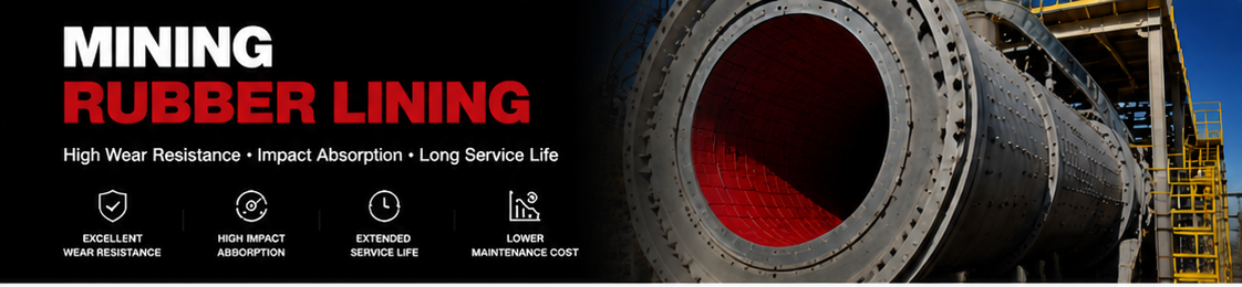
A useful specification separates impact, abrasion and environmental conditions. The table below shows the questions that help define each zone.
| Observed condition | Information to collect | Selection focus |
|---|---|---|
| Heavy wear at the loading point | Drop height, largest particle size, feed direction and throughput | Impact zone layout, liner support and local thickness |
| Long polished wear path | Material type, flow direction, speed and chute angle | Abrasion resistance, surface continuity and joint position |
| Torn edges or lifted joints | Fixing method, substrate condition, edge exposure and vibration | Panel size, edge protection and installation details |
| Material build-up | Moisture, fines, temperature, surface angle and cleaning practice | Surface finish, geometry and maintenance access |
| Uneven wear between sides | Feed alignment, chute geometry and changing operating conditions | Wear-zone mapping and asymmetric panel layout |
Photographs are helpful when they include a scale, but they should be combined with dimensions or an equipment drawing. A close-up image alone cannot confirm panel size, liner thickness or the relationship between the impact point and the discharge.
Natural rubber and natural-rubber blends are commonly considered for mining wear protection where resilience, impact absorption and resistance to abrasive mineral handling are important. The final compound must still be checked against the complete operating environment.
Identify the ore, aggregate or process material, including approximate particle size and whether it is sharp, rounded, dry, wet or mixed with slurry. The same chute geometry can create a different wear pattern when the material changes.
Provide normal and maximum operating temperatures and list any oils, reagents, cleaning chemicals or other substances that contact the liner. Do not assume that a general-purpose rubber compound is compatible with every process fluid.
Hardness is only one part of liner selection. A quotation should relate hardness to compound type, impact duty, abrasion conditions, panel dimensions and fixing method. Selecting a liner only by Shore A value can overlook the geometry and wear mechanism that control actual service behaviour.
Rubber chute liner thickness should be based on wear severity, available clearance, equipment geometry and the planned replacement method. A thicker sheet is not automatically the correct answer if it interferes with material flow, reduces the chute opening or creates difficult joints.
The loading point may need a different layout from the downstream sliding surface. Mark the zones on the drawing and specify whether each panel is intended for direct impact, sliding abrasion or a transition between the two.
Panel dimensions should allow practical handling and replacement while keeping joints away from concentrated impact where possible. Small complex areas may require cut pieces, while broad flat sections can use larger panels if installation access permits.
Curved walls, narrow outlets and changing chute angles should be measured carefully. Templates, CAD files or marked-up fabrication drawings are more reliable than overall length and width alone.
| Design item | Buyer question | Quotation input |
|---|---|---|
| Thickness | What is the current wear rate and available clearance? | Existing thickness, measured wear and requested range |
| Panel dimensions | Can the panel be installed and replaced through the available access? | Drawing, access opening and preferred panel identification |
| Joint layout | Are joints exposed to direct impact or material entry? | Flow direction and wear-zone drawing |
| Edge detail | Can material catch an exposed leading edge? | Installation direction and edge-protection requirement |
| Substrate | Is the chute surface flat, curved, corroded or repaired? | Steel condition, radius and preparation plan |
The fixing method affects liner preparation, panel size, edge details and maintenance work. Confirm the intended method before production so the supplied panels match the installation plan.
Bonded systems require a clean, dry and properly prepared substrate plus an adhesive system suitable for the rubber, steel and operating environment. Surface preparation and curing requirements should follow the selected installation procedure.
Bolted panels can support planned replacement, but hole positions, fastener protection, backing details and access from the reverse side must be defined. Drawings should show hole centres and panel orientation rather than relying on dimensions taken from a worn part.
Retainer bars, clamping arrangements or other mechanical systems may be used where they match the equipment design. The buyer should provide the existing detail and identify any locations where material has entered behind the liner.
Installation responsibility and procedures should be agreed between the equipment owner, installer and supplier. Qihang Rubber can review dimensions and fabrication information, but site preparation and installation conditions must be confirmed for each project.
A scheduled inspection should record where the liner is thinning, tearing, lifting or separating at joints. Comparing the wear map with operating changes can improve the next liner layout.
Do not discard a worn liner before recording its thickness, location and orientation. A marked sample or a dimensioned photograph can provide useful information for the replacement drawing.
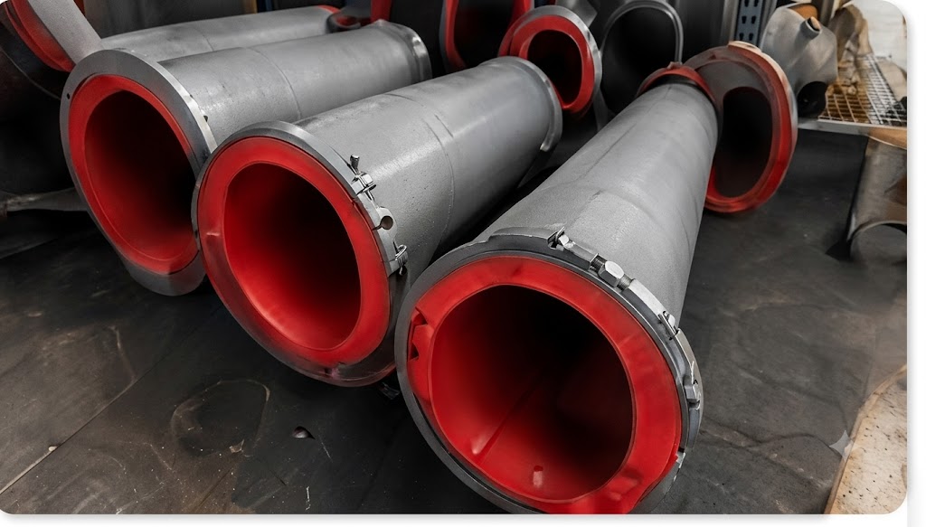
A complete RFQ reduces assumptions and allows the supplier to review the application before confirming material and dimensions. Include as much of the following information as possible:
If a drawing is unavailable, send overall dimensions plus close-up and wide-angle photographs with a visible scale. Identify the impact point and material-flow direction directly on the images.
Rubber chute liners may be supplied as sheets, cut panels or drawing-based replacement pieces, subject to technical review. For repeat orders, a numbered liner schedule helps purchasing and maintenance teams match each part to its location.
Before requesting custom fabrication, confirm tolerances, hole positions, surface finish, color, quantity and whether dimensions refer to the steel substrate or the finished liner. For reverse-engineered parts, worn edges should not be treated as original dimensions without checking the equipment drawing.
Review the Mining Rubber Lining product page for available sheet dimensions, typical material information and OEM quotation inputs. For broader wear-protection planning, read the Mining Rubber Lining wear-resistant solution guide.
For a detailed comparison of rubber sheet dimensions, impact conditions and RFQ requirements, see the wear-resistant rubber sheet for mining selection guide.
For a focused review of liner thickness and Shore A selection by equipment duty, read the Mining Rubber Lining thickness and hardness selection guide.
Natural rubber or a natural-rubber blend is commonly considered for abrasive mineral handling and impact service. The final compound should be confirmed against the material handled, temperature, chemicals, fixing method and wear mechanism.
Thickness depends on impact severity, sliding wear, available clearance, panel size and the planned replacement interval. Provide the existing liner thickness and wear-zone information so the supplier can review the requested range.
Cut-to-size and drawing-based panels can be reviewed when the buyer supplies clear dimensions, hole positions, radii, quantities and panel identification. Complex shapes may require CAD files or physical templates.
The choice depends on the equipment design, substrate, access, maintenance plan and operating environment. Confirm the fixing method before production because it affects panel preparation and dimensions.
Possible causes include exposed leading edges, poor substrate preparation, unsuitable bonding conditions, material entering behind the liner, vibration or a panel layout that places joints in a concentrated wear zone.
Send the equipment drawing or measured template, material handled, operating conditions, existing liner information, quantity, wear photographs, fixing method and destination. Marking the flow direction and impact point is especially useful.
Send your chute drawing, liner schedule, dimensions and wear photographs through the Qihang Rubber contact form. Include the material handled, impact conditions, required quantity and destination so the team can review the application and prepare a project-specific quotation.
For broader equipment and service-condition planning, see the Rubber Lining for Mineral Processing Equipment Selection Guide before choosing chute liner thickness and panel layout.
Tianjin Qihang Plastic Technology Co., Ltd
12+ Years Expertise in Industrial Rubber Sheet Manufacturing • Global Export Leader • REACH/RoHS Certified
...[ Read More >>]


