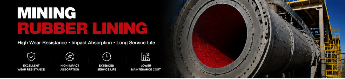
Selecting mining rubber lining is not simply a matter of choosing the thickest sheet or the highest hardness. A liner must match the equipment geometry, the material being handled, the dominant wear mechanism, installation limits and the maintenance plan. A specification that works in a low-impact slurry pipe may not be suitable for a chute receiving coarse falling ore, even when both applications use natural rubber.
This guide explains how engineers and procurement teams can organize the information needed to select mining rubber lining thickness and hardness for ball mills, chutes, hoppers, slurry pumps, pipes and tanks. The guidance is intended for project planning and RFQ preparation. Final dimensions and compound selection should be confirmed against equipment drawings and actual operating conditions.
When the application is an abrasive slurry pipeline, use the slurry pipe rubber lining guide to organize pipe dimensions, wear zones, material conditions and installation requirements before finalizing thickness and hardness.
Thickness determines how much sacrificial material is available before the liner reaches its replacement limit. It also affects panel weight, flexibility, clearances, joint design and the method used to secure the lining. Hardness influences how the rubber deforms under impact, how it supports the material load and how it responds to sliding or hydraulic abrasion.
These two properties interact. A thick but unsuitable compound can still wear unevenly, lift at a joint or interfere with equipment clearance. A correctly selected compound can also perform poorly when the panel is too thin for the local impact zone or too rigid to follow the substrate geometry. For this reason, the thickness and hardness decision should be made as one system rather than as two isolated purchase specifications.
Before discussing millimetres or Shore A values, identify what is actually removing material from the equipment surface. Most mining duties combine several mechanisms, but one or two usually dominate each wear zone.
Sliding abrasion occurs when ore, concentrate, sand or other solids move continuously across a surface. Particle angularity, material velocity, load, moisture and the angle between the material flow and the liner all affect the wear pattern. Pipes, launders and some chute surfaces often show long directional wear marks caused by this mechanism.
Impact becomes important where material drops onto a chute, hopper or mill component. Large or sharp particles can concentrate energy in a small area and may also cut the rubber surface. The drop height, feed size distribution, feed rate and impact angle should therefore be included in the liner review.
Slurry wear depends on solids concentration, particle size, velocity, turbulence and changes in flow direction. Pump casings, bends, reducers and pipe transitions may wear differently from straight pipe sections. A general line specification may need local reinforcement at these high-turbulence locations.
Rubber repeatedly compresses and recovers under load. Excessive movement at unsupported edges, joints or fasteners can create local fatigue even when the broad liner surface remains serviceable. Panel layout and substrate support are therefore part of the selection process.
A useful selection review begins with operating data. When exact data is unavailable, clearly mark estimates so they can be checked during engineering approval.
Photos are helpful, but they should include a scale and show the entire wear zone. Marked-up drawings are more reliable for fabrication because they identify dimensions, hole positions, seams and protected edges.
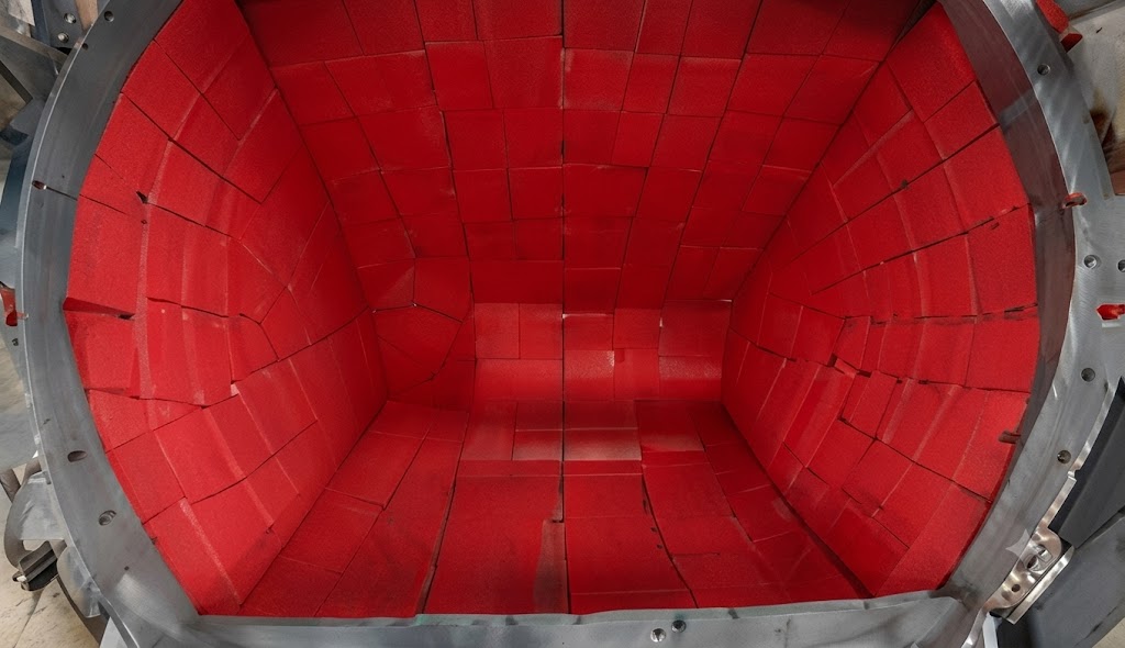
Qihang Rubber's mining lining product is available in standard thicknesses from 3 mm to 50 mm. This range describes manufacturing capability; it does not mean every thickness is suitable for every machine. Begin with the equipment duty and then check the physical constraints that may limit the selection.
| Application | Dominant design question | Thickness direction to review | Drawing details required |
|---|---|---|---|
| Ball mill lining | How are impact, grinding action and liner movement distributed? | Review impact zones, liner profile, attachment and internal clearance together | Shell diameter, liner layout, hole pattern, lifting profile and media conditions |
| Chute or hopper | Where does falling material first strike and where does it change direction? | Consider local reinforcement or thicker replaceable panels at strike zones | Drop height, feed direction, impact area, panel seams and mounting method |
| Slurry pump | Where are velocity and turbulence highest inside the wet-end geometry? | Match thickness to casing clearance, flow passage and local erosion pattern | Pump model, component drawing, slurry data and existing wear map |
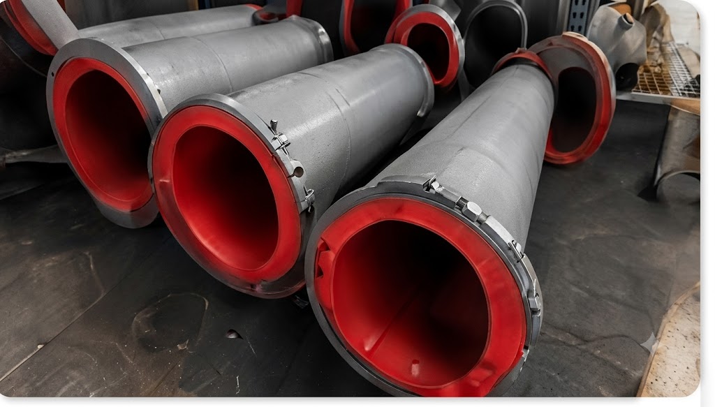
| Pipe or bend | Which sections experience directional erosion or turbulence? | Check straight runs separately from bends, reducers, tees and transitions | Inside diameter, bend radius, flange details, flow direction and installation length |
| Tank or process vessel | Is the main duty abrasion, impact, corrosion isolation or a combination? | Balance coverage, flexibility, seam layout and access for installation | Vessel geometry, nozzles, agitator clearance, temperature and process media |
Ball mill liners operate inside a constrained rotating system. Thickness affects internal volume, lifting geometry, fastener engagement and the relationship between the shell and the grinding load. Procurement teams should not replace a mill liner specification solely by matching the nominal thickness of a flat sheet. The complete liner profile, attachment arrangement and duty must be reviewed.
A chute may contain several wear zones: the primary strike point, the sliding bed, changes in direction, side walls and discharge lips. One uniform thickness can be convenient, but it may not be the most practical maintenance layout. Replaceable panels or localized thickness changes can concentrate material where it is needed and simplify future shutdown work.
Pump components have tight flow passages and shaped surfaces. Added thickness must not restrict the hydraulic path or interfere with assembly. The correct review therefore uses the pump model and component drawing together with slurry concentration, particle size and observed wear locations.
Straight pipe sections may experience relatively stable directional flow, while bends and reducers create secondary flow and local turbulence. Tanks may combine wall abrasion, inlet impact and agitation. Separate these zones during the review instead of assuming that one line-wide or vessel-wide thickness is automatically correct.
The standard Mining Rubber Lining product lists a typical hardness of 35-45 Shore A. This range suits many natural-rubber wear applications, but the exact target should be evaluated with the compound formulation, thickness, temperature and duty. Shore A is a useful quality-control and specification value, yet it does not by itself predict service life.
| Hardness direction | Potential behaviour to evaluate | Questions for the project team |
|---|---|---|
| Lower end of the specified range | More deformation and energy absorption, with greater need to check support and movement | Is impact dominant? Are edges and joints fully supported? Will temperature increase softness? |
| Middle of the specified range | Balanced resilience and support for mixed abrasion and impact duties | Does the existing successful liner fall near this range? Are wear zones mixed? |
| Higher end of the specified range | Less deformation and firmer support, with impact and flexibility still requiring review | Is sliding abrasion dominant? Must the liner follow tight curvature? Are fasteners protected? |
Do not compare hardness numbers without confirming the test scale, specimen condition and acceptance tolerance. A supplier drawing or quality document should clearly state Shore A when that is the required scale.
Many mining applications contain both impact and abrasion. In these cases, selection is a compromise among energy absorption, surface support, available wear allowance and equipment geometry. The following process keeps the decision practical:
When previous liners are available, measure the remaining thickness at several locations and compare the results with operating hours. A wear map is more useful than one average number because it shows where the next design should add material or change panel layout.
Temperature changes rubber stiffness and can affect bonding systems. Process water, oils, reagents or cleaning chemicals may also influence compound selection. Natural rubber is widely selected for abrasion and resilience, but it should not be assumed compatible with every fluid or temperature condition.
Include both normal and upset conditions in the RFQ. If the process contains oil, unusual chemicals, prolonged heat or cleaning cycles, identify the media and concentration so the supplier can review whether an NR compound or another elastomer family is more appropriate.
Thickness cannot be separated from installation. A larger or thicker panel is heavier and may be more difficult to position inside confined equipment. Curved surfaces may require narrower panels, formed parts or a different seam arrangement. Bonded sheets, mechanically fastened panels and molded components also have different edge and preparation requirements.
A lining specification becomes more valuable when it includes a way to evaluate performance. During planned shutdowns, inspect strike zones, seams, edges, fasteners, bends and transitions. Record remaining thickness at consistent measurement points and photograph the same locations over time.
Replacement criteria should be based on equipment protection and process risk, not only on whether rubber remains visible. Local lifting, exposed substrate, damaged joints or restricted flow may require action before the average panel thickness reaches a general limit.
For a project-specific review, send the following information where available:
If some values are unknown, send the equipment model and available drawings first. The missing items can then be listed for technical confirmation before quotation.
Review the Mining Rubber Lining product page for the available product dimensions and typical material data. The Wear-Resistant Natural Rubber Sheet page provides additional sheet information for fabrication and wear protection.
For transfer points, read the Rubber Chute Liners for Mining guide. For a broader material and RFQ overview, use the Wear Resistant Rubber Sheet for Mining guide and the Mining Rubber Lining wear-protection guide.
No. Additional thickness may provide more wear allowance, but it can also affect clearance, panel weight, flexibility, fasteners and internal equipment geometry. The correct value depends on the wear zone and machine design.
The Qihang Rubber product lists a typical range of 35-45 Shore A. The final target should be confirmed against impact, abrasion, temperature, geometry and support conditions.
It can be specified for manufacturing simplicity, but the strike point, sliding bed, side walls and discharge area often experience different wear. A zoned panel layout may be more practical for maintenance.
Provide the mill model, shell dimensions, liner profile, hole pattern, grinding conditions, current liner specification and observed wear pattern. Nominal sheet thickness alone is not enough to confirm a mill liner design.
Identify the flow direction, inside diameter, bend radius, slurry conditions and where wear is concentrated. Bends, reducers and tees should be reviewed separately from straight pipe runs.
Cut-to-size and drawing-based production can be reviewed. Supply clear dimensions, tolerances, hole positions, quantities and operating conditions so manufacturability can be checked before quotation.
Thickness and hardness selection works best when the supplier receives equipment information before the order specification is fixed. Send drawings, wear photos and operating conditions through the Qihang Rubber contact form. The project details can then be reviewed against available natural-rubber lining specifications and fabrication options.
Tianjin Qihang Plastic Technology Co., Ltd
12+ Years Expertise in Industrial Rubber Sheet Manufacturing • Global Export Leader • REACH/RoHS Certified
...[ Read More >>]


