A mining rubber lining rarely fails without leaving clues. The first signs may be a thin edge near a joint, a small blister under a bonded panel, exposed steel at a transfer point, or a wear pattern that appears only after the feed material changes. Treating every problem as a request for a thicker rubber sheet can hide the real cause and lead to another premature replacement.
This guide is written for maintenance engineers, plant managers, equipment builders and buyers who need to investigate a worn rubber liner and prepare a practical replacement enquiry. It explains how to separate material wear from installation or process problems, what to record during inspection, and which details a supplier needs before recommending a replacement mining rubber lining.
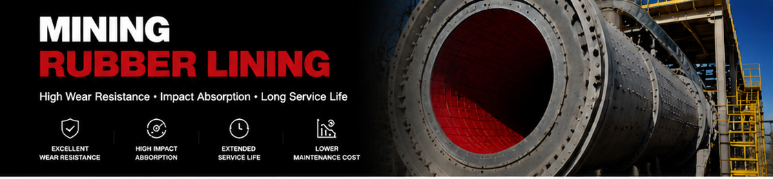
Inspection should begin with the visible pattern rather than with a preferred material or thickness. Different failure patterns point to different questions:
Photograph the entire equipment area first, then take close images of representative wear. Place a ruler or another dimension reference beside the damaged area when possible. A close-up without scale can show the symptom but not its severity.
A worn surface and a detached lining require different corrective thinking. Abrasion gradually removes rubber from the exposed face. Detachment separates the lining from the substrate or opens a joint, sometimes while much of the rubber thickness is still present.
Check whether the damaged area follows a panel edge, bolt line, weld, corner or change in equipment geometry. If it does, inspect the support and attachment details before specifying a new sheet. A replacement with the same material may behave in the same way if the edge remains exposed or the substrate is not prepared correctly.
For bonded linings, review surface preparation, cleanliness, moisture, adhesive compatibility, curing conditions and the condition of the steel. For mechanically retained panels, inspect holes, fasteners, backing surfaces, seating and the condition of the joint. Do not infer the cause from the appearance of the rubber alone.
Sliding abrasion, direct impact, cutting, gouging and repeated flexing do not load a liner in the same way. A chute can have an impact zone at the feed point and a sliding zone farther downstream. A pipe elbow can wear differently from a straight section. A pump casing and an impeller can also see different flow and contact conditions.
Map where the material first strikes, where it changes direction and where it accelerates. Compare that flow map with the actual worn areas. The comparison is often more useful than a general request for the most wear-resistant rubber.
Ore type, particle size, moisture, solids content, throughput, drop height and flow speed can change over time. A lining selected for one duty may show a new wear pattern after production conditions change. Record the condition at the time of inspection, including any recent change in feed material or operating rate.
A thicker liner provides additional wear allowance in some applications, but it also changes weight, flexibility, flow area, component clearance and installation effort. On pumps and other close-fitting equipment, excess thickness can affect internal geometry. On chutes and hoppers, it can reduce the available passage or create an exposed step at a transition.
Review thickness together with the wear severity, equipment drawing, panel support and attachment method. A zoned layout can be more practical than applying one thickness everywhere, provided the transitions are supported and the flow direction is considered.
Rust scale, oil, moisture, sharp welds, deformation and contamination can compromise a lining installation. Inaccessible corners and poorly planned joints can make a suitable rubber difficult to fit and maintain. Installation is part of the specification, not an afterthought after the material has been purchased.
Natural rubber is often considered for wet abrasive service, but the complete environment still matters. Oil, fuel, cleaning chemicals, solvents, elevated temperature, outdoor exposure and unusual additives may affect the suitability of a compound. Confirm the actual medium and temperature instead of relying only on a product label such as wear resistant.
A consistent inspection record makes supplier discussions faster and helps compare the next replacement with the previous one. Use the following sequence during a planned shutdown or safe inspection:
Do not enter an operating area or remove a liner until the site鈥檚 own isolation, access and inspection procedures have been followed. The technical value of a measurement is lost if it was taken without a reliable reference point or under an unsafe condition.
Use this table during a safe inspection. Record measured values and observations rather than filling in assumed specifications.
| Parameter | What to record | Why it matters |
|---|---|---|
| Equipment type | Chute, hopper, pipe, tank, slurry pump or another item | Helps define the lining design and inspection scope. |
| Wear location | Feed zone, elbow, joint, outlet, corner or panel edge | Shows where the main loading or failure is occurring. |
| Remaining thickness | Original thickness and readings from normal and damaged areas | Supports a review of wear severity and remaining allowance. |
| Wear pattern | Sliding, impact, cutting, gouging, blistering, cracking or lifting | Helps separate material wear from attachment or process problems. |
| Flow direction | Material entry, impact point, change of direction and discharge path | Helps compare the actual loading pattern with the worn area. |
| Attachment condition | Bonded, bolted, lifted edge, open joint or detached area | Identifies installation details that may need correction. |
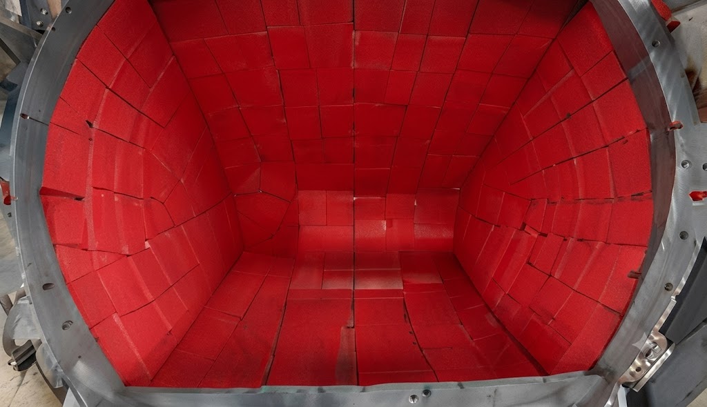
Look for a difference between the feed zone, side walls, transition points and outlet. A shifted trajectory can move the impact zone away from the original design. Check panel orientation and upstream edges because a small exposed edge can become a starting point for lifting or cutting.
For a new chute or hopper lining enquiry, provide the internal dimensions, material-flow direction, drop height, handled material, panel layout, thickness and fastening preference. Photos should show the complete flow path, not only the damaged panel.
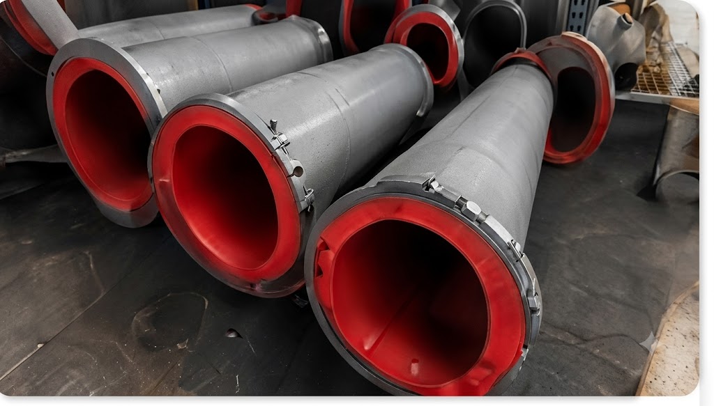
Straight pipe, bends, reducers, branches and inlet areas can have different wear patterns. Confirm the internal diameter after lining, bend radius, flange faces, sealing areas, joint treatment and any restricted clearances. A pipe or tank drawing is more useful than nominal size alone.
For slurry pumps, identify the casing, impeller, side liner, suction area, discharge passage and other wetted components separately. Record the pump model, part number, slurry solids, particle characteristics, speed, pressure, temperature and observed wear location. A replacement component must match the equipment geometry and required clearances.
Our slurry pump rubber lining selection guide covers pump wear zones and the information needed for a more complete RFQ.
Whether a liner can be repaired depends on the remaining material, the size and location of the damage, the attachment system, access, contamination and the operating risk of leaving a weak area in service. A small, accessible local defect may be reviewed differently from a lifted edge in a high-flow zone or widespread loss of thickness.
Use the inspection record to define the scope. The supplier may need to review a local patch, a replacement panel, a complete lining section or a redesigned attachment detail. Do not describe every case as a full replacement before the equipment geometry and failure pattern have been assessed.
A clear replacement request reduces back-and-forth questions and makes quotations easier to compare. Include:
Share the following information with the supplier where it is available. Unknown values can be marked for review rather than guessed.
| Parameter | Information to provide |
|---|---|
| Equipment identity | Manufacturer, model, part number and the name of the component or section |
| Dimensions and geometry | Length, width, thickness, internal diameter, bend radius, panel shape and clearances |
| Material handled | Ore, coal, sand, tailings, mineral slurry or another bulk material |
| Particle and process data | Particle size, shape, solids content, moisture, flow rate, pressure and temperature |
| Existing liner | Rubber type, thickness, hardness, attachment method and service history if known |
| Failure evidence | Wear location, remaining thickness readings, photographs and marked-up drawings |
| Replacement scope | Quantity, cutting or fabrication details, installation preference and destination |
When some information is unavailable, state that clearly and send the evidence you do have. A service photograph, a marked-up drawing and a short wear history can give a supplier a better starting point than a generic request for replacement rubber liner.
After the replacement is installed, keep a simple record of the starting condition. Note the material, thickness, hardness, panel locations, attachment method and initial operating settings. At each inspection, photograph the same reference points and record the wear depth or visible change.
This creates a useful service history. It can show whether a problem is linked to one corner, one joint, one feed condition or the full surface. It also gives the next supplier more than a single failure photograph when the equipment needs another review.
No. The cause may be impact, flow change, exposed joints, poor attachment, substrate condition or material compatibility. Thickness should be reviewed with the complete service condition and available clearance.
Provide an overview of the equipment, a view showing material flow, close-ups of the worst wear and images of joints or attachment details. Include a ruler or another scale reference when possible.
A worn sample may help, but it should be accompanied by dimensions, equipment details, service conditions, attachment information and photographs. The sample alone may not show why the lining failed.
The equipment geometry, handled material, wear mechanism, current specification, failure location, drawings or measurements and required quantity are the most useful starting points. Temperature and chemical exposure should also be stated.
Qihang Rubber supplies mining rubber lining and wear-resistant natural rubber sheet for abrasive equipment applications. Send the equipment drawing, worn-area photographs, operating conditions, dimensions and required quantity through the Qihang Rubber inquiry form.
For related selection work, review the slurry pipe rubber lining guide and the mining rubber lining thickness and hardness guide. A defined failure record gives the supplier a better basis for discussing material, thickness, fabrication and installation.
For equipment selection by service condition, see the Rubber Lining for Mineral Processing Equipment Selection Guide.
Tianjin Qihang Plastic Technology Co., Ltd
12+ Years Expertise in Industrial Rubber Sheet Manufacturing • Global Export Leader • REACH/RoHS Certified
...[ Read More >>]


